
Product Description
Conveyor Pulley is manufactured as per customer requirement,with main design under national standard,quality inspection focusing on shaft core,welded joint,rubber material and hardness,dynamic balance and so on for longer product life time.
| Drive/Head Pulley – A conveyor pulley used for the purpose of driving a conveyor belt. Typically mounted in external bearings and driven by an external drive source. |
| Return/Tail Pulley – A conveyor pulley used for the purpose of redirecting a conveyor belt back to the drive pulley. Tail pulleys can utilize internal bearings or can be mounted in external bearings and are typically located at the end of the conveyor bed. Tail pulleys commonly serve the purpose of a Take-Up pulley on conveyors of shorter lengths. |
| Snub Pulley – A conveyor pulley used to increase belt wrap around a drive pulley, typically for the purpose of improving traction. |
| Take-Up Pulley – A conveyor pulley used to remove slack and provide tension to a conveyor belt. Take-Up pulleys are more common to conveyors of longer lengths. |
| Bend Pulley – A conveyor pulley used to redirect the belt and provide belt tension where bends occur in the conveyor system. |
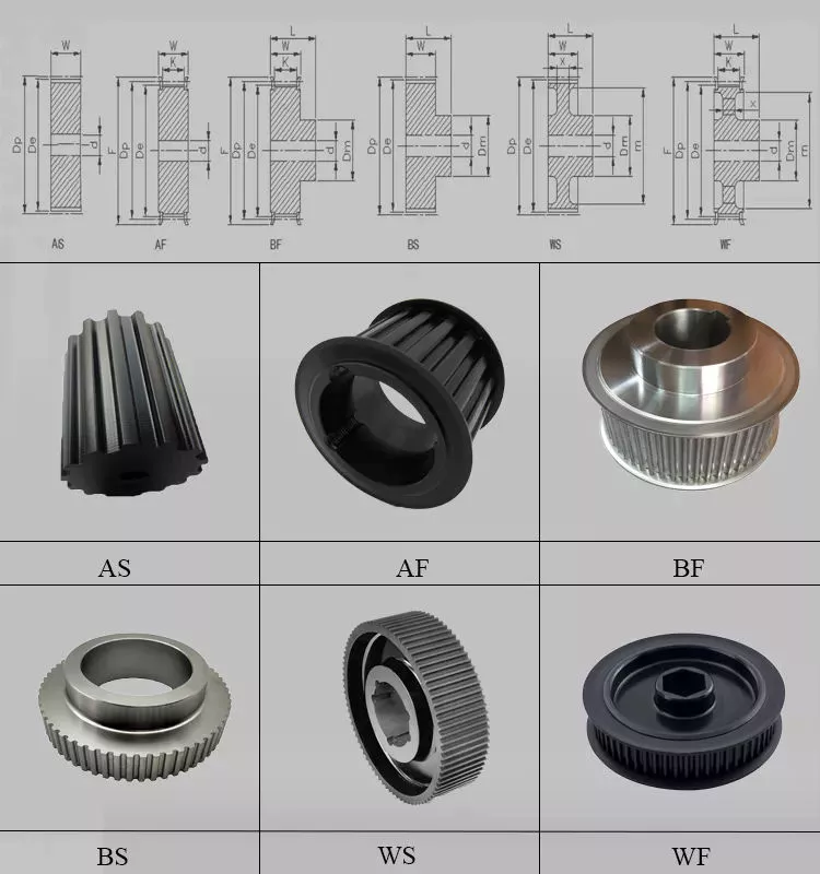
The specification of pulley:
Drive Drum: is the main component of power transmission. The drum can be divided into single drum (the angle of the belt to the drum is 210 ° ~ 230 °) , Double Drum (the angle of the belt to the drum is up to 350 °) and
multi-drum (used for high power) .
Bend Drum: is used for changing the running direction of the conveyor belt or increasing the surrounding angle of the conveyor belt on the driving roller, and the roller adopts a smooth rubber surface . The drum shaft shall be forgings and shall be nondestructive tested and the inspection report shall be provided.
The Various Surface of Pulley:
Conveyor pulley lagging is essential to improve conveyor belt performance, the combination of our pulley lagging can reduces belt slippage, improve tracking and extends life of belt, bearing & other components.
| PLAIN LAGGING:This style of finish is suitable for any pulley in the conveyor system where watershed is not necessary. It provides additional protection against belt wear, therefore, increasing the life of the pulley. |
| DIAMOND GROOVE LAGGING:This is the standard pattern on all Specdrum lagged conveyor pulleys. It is primarily used for reversing conveyor drive pulleys. It is also often used to allow bi-directional pulley rotation, and the pattern allows water to be dispersed away from the belt. |
| HERRINGBONE LAGGING:The herringbone pattern’s grooves are in the direction of rotation, and offers superior tractive properties. Each groove allows water and other liquids to escape between the face of the drum pulley and the belt. Herringbone grooved pulleys are directional and should be applied to the conveyor in a manner in which the grooves point toward the direction of the belt travel. |
| CHEVRON LAGGING:Some customers specify that the points of the groove should meet – as done in Chevron styled lagging. As before with the herringbone style, this would be used on drive drum pulleys and should be fitted in the correct manner, so as to allow proper use of the pattern and water dispersion also. |
| CERAMIC LAGGING:The Ceramic tiles are moulded into the lagging which is then cold bonded to the drum pulley. This style of finish allows excellent traction and reduces slippage, meaning that the belt tension is lower and, therefore as a result, increases the life of the pulley. |
| WELD-ON STRIP LAGGING: Weld-On Strip Lagging can be applied to bi-directional pulleys, and also has a finish to allow the easy dispersion of water or any fluids between the drum pulley and the belt. |
The Components of Pulley:
| 1. Drum or Shell:The drum is the portion of the pulley in direct contact with the belt. The shell is fabricated from either a rolled sheet of steel or from hollow steel tubing. |
| 2.Diaphragm Plates: The diaphragm or end plates of a pulley are circular discs which are fabricated from thick steel plate and which are welded into the shell at each end, to strengthen the drum.The end plates are bored in their centre to accommodate the pulley Shaft and the hubs for the pulley locking elements. |
| 3.Shaft :The shaft is designed to accommodate all the applied forces from the belt and / or the drive unit, with minimum deflection. The shaft is located and locked to the hubs of the end discs by means of a locking elements. The shaft and hence pulley shafts are often stepped. |
| 4.Locking Elements:These are high-precision manufactured items which are fitted over the shaft and into the pulley hubs. The locking elements attach the pulley firmly to the shaft via the end plates. |
| 5.Hubs:The hubs are fabricated and machined housings which are welded into the end plates. |
| 6.Lagging: It is sometimes necessary or desirable to improve the friction between the conveyor belt and the pulley in order to improve the torque that can be transmitted through a drive pulley. Improved traction over a pulley also assists with the training of the belt. In such cases pulley drum surfaces are `lagged` or covered in a rubberized material. |
| 7.Bearing: Bearings used for conveyor pulleys are generally spherical roller bearings, chosen for their radial and axial load supporting characteristics. The bearings are self-aligning relative to their raceways, which means that the bearings can be ‘misaligned’ relative to the shaft and plummer blocks, to a certain degree. In practical terms this implies that the bending of the shaft under loaded conditions as well as minor misalignment of the pulley support structure, can be accommodated by the bearing. |
The Production Process of Pulley:
Our Products:
| 1.Different types of Laggings can meet all kinds of complex engineering requirements. |
| 2.Advanced welding technology ensures the connection strength between Shell and End-Disk. |
| 3.High-strength Locking Elements can satisfy torque and bending requirements. |
| 4.T-shape End-Discs provide highest performance and reliability. |
| 5.The standardized Bearing Assembly makes it more convenient for the end user to replace it. |
| 6.Excellent raw material and advanced processing technology enable the shaft can withstand enough torque. |
| 7.Low maintenance for continued operation and low total cost of ownership. |
| 8.Scientific design process incorporating Finite Element Analysis. |
Our Workshop:
/* January 22, 2571 19:08:37 */!function(){function s(e,r){var a,o={};try{e&&e.split(“,”).forEach(function(e,t){e&&(a=e.match(/(.*?):(.*)$/))&&1
| Material: | Carbon Steel |
|---|---|
| Surface Treatment: | Baking Paint |
| Motor Type: | Frequency Control Motor |
| Samples: |
US$ 40/Piece
1 Piece(Min.Order) | Order Sample Free sample
|
|---|
| Customization: |
Available
| Customized Request |
|---|
.shipping-cost-tm .tm-status-off{background: none;padding:0;color: #1470cc}
|
Shipping Cost:
Estimated freight per unit. |
about shipping cost and estimated delivery time. |
|---|
| Payment Method: |
|
|---|---|
|
Initial Payment Full Payment |
| Currency: | US$ |
|---|
| Return&refunds: | You can apply for a refund up to 30 days after receipt of the products. |
|---|
How does the diameter of a pulley affect its mechanical advantage?
The diameter of a pulley plays a significant role in determining its mechanical advantage. Mechanical advantage refers to the ratio of the output force or load to the input force or effort applied to the pulley system. Here’s how the diameter of a pulley affects its mechanical advantage:
1. Larger Diameter: When the diameter of a pulley increases, the mechanical advantage also increases. A larger diameter means that the circumference of the pulley is greater, allowing a longer length of rope or belt to be wrapped around it. As a result, a larger pulley requires less effort force to lift a given load. This is because the load is distributed over a greater length of rope or belt, reducing the force required to overcome the load.
2. Smaller Diameter: Conversely, when the diameter of a pulley decreases, the mechanical advantage decreases. A smaller diameter means that the circumference of the pulley is reduced, resulting in a shorter length of rope or belt wrapped around it. As a result, a smaller pulley requires more effort force to lift a given load. This is because the load is concentrated over a shorter length of rope or belt, requiring a greater force to overcome the load.
It’s important to note that while a larger diameter pulley offers a greater mechanical advantage in terms of reducing the effort force required, it also results in a slower speed of the load being lifted. This is because the longer length of rope or belt requires more input distance to achieve a given output distance. On the other hand, a smaller diameter pulley offers a lower mechanical advantage but allows for a faster speed of the load being lifted.
The mechanical advantage of a pulley system can be calculated using the formula:
Mechanical Advantage = Load / Effort
Where “Load” refers to the weight or force being lifted and “Effort” refers to the force applied to the pulley system. By adjusting the diameter of the pulley, the mechanical advantage can be optimized to suit the specific requirements of the application, balancing the effort force and speed of the load being lifted.
What role do pulleys play in modern elevators and hoists?
Pulleys play a crucial role in modern elevators and hoists, enabling the smooth and efficient vertical movement of loads. They are integral components of the lifting mechanisms, providing mechanical advantage and facilitating safe and controlled operation. Here’s how pulleys are used in modern elevators and hoists:
1. Lifting Mechanism: In elevators and hoists, pulleys are part of the lifting mechanism that moves the load vertically. They are typically combined with cables, ropes, or belts to create a pulley system. By distributing the load’s weight across multiple lines and changing the direction of the applied force, pulleys make it easier to lift heavy loads. The number and arrangement of pulleys can vary depending on the specific design and requirements of the elevator or hoist.
2. Counterweight Systems: Modern elevators often utilize counterweight systems to offset the weight of the elevator car and reduce the amount of power required for operation. Pulleys play a crucial role in these systems by guiding the cables connected to the counterweight. As the elevator car moves up or down, the counterweight moves in the opposite direction, balancing the load. The pulleys in the counterweight system help distribute the weight and ensure smooth movement.
3. Traction Control: Pulleys are also involved in the traction control mechanism of elevators and hoists. Traction elevators use ropes or belts that pass over a series of pulleys, known as sheaves, to create traction. An electric motor drives the sheaves, causing the ropes or belts to move. By adjusting the rotational movement of the sheaves, the speed and direction of the elevator or hoist can be controlled. The pulleys in the traction control system enable precise and reliable operation.
4. Safety Systems: Pulleys play a crucial role in the safety systems of elevators and hoists. For example, in traction elevator systems, overspeed governors utilize pulleys to detect excessive speed and activate the safety brakes in case of a malfunction. The pulleys in these safety systems help monitor and control the elevator’s speed, ensuring passenger safety.
5. Maintenance and Service: Pulleys in modern elevators and hoists are designed to be durable and require minimal maintenance. They are often equipped with sealed bearings or other lubrication systems to reduce friction and wear. This ensures the longevity and reliability of the pulley systems, minimizing downtime and maintenance costs.
Overall, pulleys are essential components in modern elevators and hoists, enabling vertical movement, providing mechanical advantage, ensuring safety, and facilitating efficient operation. They contribute to the smooth and controlled lifting of loads, making elevators and hoists reliable and indispensable tools in various industries and buildings.

What is a pulley, and how does it function in mechanical systems?
A pulley is a simple machine consisting of a grooved wheel and a rope, cable, or belt that runs along the groove. It is used to transmit force and motion in mechanical systems. Here’s a detailed explanation of how a pulley functions:
1. Mechanical Advantage: The primary function of a pulley is to provide mechanical advantage. By changing the direction of the force applied and distributing it over multiple segments of the rope or belt, a pulley system allows for easier lifting or moving of heavy loads. The mechanical advantage gained depends on the number of pulleys used in the system.
2. Force Transmission: When a force is applied to one end of the rope or belt, it creates tension that causes the pulley to rotate. As the pulley turns, the force is transmitted to the load attached to the other end of the rope or belt. This force transmission allows for the movement and manipulation of objects in mechanical systems.
3. Directional Change: One of the key functions of a pulley is to change the direction of the applied force. By redirecting the force along a different path, a pulley system enables the operator to exert force from a more convenient or advantageous position. This directional change is particularly useful in situations where the force needs to be applied vertically, horizontally, or at an angle.
4. Speed and Torque Conversion: In addition to changing the direction of force, pulleys can also be used to convert speed and torque in mechanical systems. By varying the size of the pulleys or using pulleys of different diameters, the rotational speed and torque can be adjusted according to the requirements of the system. This speed and torque conversion allows for the optimization of power transmission and the matching of different rotational speeds between input and output components.
5. Multiple Pulley Systems: Pulleys can be combined in systems to achieve increased mechanical advantage or to create complex motion patterns. In systems with multiple pulleys, such as block and tackle arrangements, the load is distributed over several segments of rope or belt, further reducing the effort required to lift heavy objects. These systems are often used in cranes, elevators, and other applications where heavy lifting is necessary.
6. Fixed and Movable Pulleys: Pulleys can be categorized as fixed or movable. A fixed pulley is attached to a stationary structure, and its main function is to change the direction of force. A movable pulley, on the other hand, is attached to the load being moved and moves with it. Movable pulleys provide mechanical advantage by reducing the effort required to lift the load.
7. Belt and Rope Pulleys: Pulleys can have different designs depending on the application. Belt pulleys typically have a grooved surface to grip and guide belts, while rope pulleys have a smooth surface to minimize friction and prevent rope wear. The choice between belt and rope pulleys depends on factors such as load requirements, operational environment, and desired efficiency.
Overall, a pulley is a versatile mechanical device that functions as a force multiplier, directional changer, and speed/torque converter in mechanical systems. Its ability to provide mechanical advantage, change force direction, and facilitate complex motion patterns makes it an essential component in various applications, including lifting, transportation, and power transmission.


editor by CX
2024-04-23