Product Description
Product Description
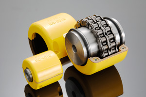
Roller chain couplings have the advantages of simple structure, convenient loading and unloading, large torque transmission, and easy operation. However, there is significant wear between the chains, especially during high-speed operation when the radial motion generated by centrifugal force will accelerate their wear. Therefore, it is not suitable for use at high speeds and under impact loads, nor for the connection of vertical shafts.
When designing the overall structure of the coupling, full attention should be paid to the lubrication and dust prevention between the tooth surface and the rollers, and an outer shell should be added. In addition to dust and oil storage, it also has a protective effect. Because if the chain breaks, it may cause personal accidents.
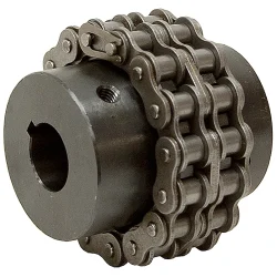
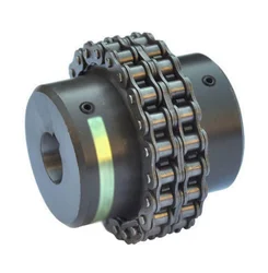
The double row sleeve roller chain coupling has formed a standard (old standard GB6069-85, new standard GB/T 6069-2002). The transmission torque and allowable speed are 4 times and 2 times that of a single row roller chain of the same size, respectively. Because when the chain size is determined, it can accommodate 2 teeth within the width of a single row of sleeve rollers, while a double row can only accommodate 1 tooth, the tooth thickness of a single row is only half of that of a double row. So, the rollers of the double row chain are located in the grooves of the main and driven sprockets, and when subjected to force, they rotate independently without interfering with each other, reducing wear.
Product Parameters
| model | Nominal torqueTnN·m | Allowable speed(n) r/min | Axis hole diameter d1,d2 | Axis hole length | Chain number | chain Pitch | Number of teeth Z | D | b1 | S | A | Dx () | Lx () | kg | Transmission inertiakg·m2 | ||
| Ymodel | J1model | ||||||||||||||||
| No cover installed | Installing cover | L | L1 | ||||||||||||||
| GL1 | 40 | 1400 | 4500 | 16 | 42 | – | 06B | 9.525 | 14 | 51.06 | 5.3 | 4.9 | – | 70 | 70 | 0.40 | 0.0571 |
| 18 | 42 | – | – | ||||||||||||||
| 19 | 42 | – | – | ||||||||||||||
| 20 | 52 | 38 | 4 | ||||||||||||||
| GL2 | 63 | 1250 | 4500 | 19 | 42 | – | 06B | 9.525 | 16 | 57.08 | 5.3 | 4.9 | – | 75 | 75 | 0.70 | 0.0571 |
| 20 | 52 | 38 | 4 | ||||||||||||||
| 22 | 52 | 38 | 4 | ||||||||||||||
| 24 | 52 | 38 | 4 | ||||||||||||||
| GL3 | 100 | 1000 | 4000 | 20 | 52 | 38 | 08B | 12.7 | 14 | 68.88 | 7.2 | 6.7 | 12 | 85 | 80 | 1.1 | 0.00038 |
| 22 | 52 | 38 | 12 | ||||||||||||||
| 24 | 52 | 44 | 12 | ||||||||||||||
| 25 | 62 | – | 6 | ||||||||||||||
| GL4 | 160 | 1000 | 4000 | 24 | 52 | – | 08B | 12.7 | 16 | 76.91 | 7.2 | 6.7 | – | 95 | 88 | 1.8 | 0.0 |
| 25 | 62 | 44 | 6 | ||||||||||||||
| 28 | 62 | 44 | 6 | ||||||||||||||
| 30 | 82 | 60 | – | ||||||||||||||
| 32 | 82 | 60 | – | ||||||||||||||
| GL5 | 250 | 800 | 3150 | 28 | 62 | – | 10A | 15.875 | 16 | 94.46 | 8.9 | 9.2 | – | 112 | 100 | 3.2 | 0.0571 |
| 30 | 82 | 60 | – | ||||||||||||||
| 32 | 82 | 60 | – | ||||||||||||||
| 35 | 82 | 60 | – | ||||||||||||||
| 38 | 82 | 60 | – | ||||||||||||||
| 40 | 112 | 84 | – | ||||||||||||||
| GL6 | 400 | 630 | 2500 | 32 | 82 | 60 | 10A | 15.875 | 20 | 116.57 | 8.9 | 9.2 | – | 140 | 105 | 5.0 | 0.0058 |
| 35 | 82 | 60 | – | ||||||||||||||
| 38 | 82 | 60 | – | ||||||||||||||
| 40 | 112 | 84 | – | ||||||||||||||
| 42 | 112 | 84 | – | ||||||||||||||
| 45 | 112 | 84 | – | ||||||||||||||
| 18 | 112 | 84 | – | ||||||||||||||
| 50 | 112 | 84 | – | ||||||||||||||
| GL7 | 630 | 630 | 2500 | 40 | 112 | 60 | 12A | 19.05 | 18 | 127.78 | 11.9 | 10.9 | – | 150 | 122 | 7.4 | 0.012 |
| 42 | 112 | 60 | – | ||||||||||||||
| 45 | 112 | 60 | – | ||||||||||||||
| 48 | 112 | 84 | – | ||||||||||||||
| 50 | 112 | 84 | – | ||||||||||||||
| 55 | 112 | 84 | – | ||||||||||||||
| 60 | 142 | 107 | – | ||||||||||||||
| GL8 | 1000 | 500 | 2240 | 45 | 112 | 84 | 16A | 25.40 | 16 | 154.33 | 15.0 | 14.3 | 12 | 180 | 135 | 11.1 | 0.571 |
| 48 | 112 | 84 | 12 | ||||||||||||||
| 50 | 112 | 84 | 12 | ||||||||||||||
| 55 | 112 | 84 | 12 | ||||||||||||||
| 60 | 142 | 107 | – | ||||||||||||||
| 65 | 142 | 107 | – | ||||||||||||||
| 70 | 142 | 107 | – | ||||||||||||||
| GL9 | 1600 | 400 | 2000 | 50 | 112 | 84 | 16A | 25.4 | 20 | 186.50 | 15.0 | 14.3 | 12 | 215 | 145 | 20.0 | 0.061 |
| 55 | 112 | 84 | 12 | ||||||||||||||
Packaging & Shipping
After Sales Service
If during transportation or if the customer receives the goods, opens the packaging and finds any damage, they can resend a new product to the customer.
/* January 22, 2571 19:08:37 */!function(){function s(e,r){var a,o={};try{e&&e.split(“,”).forEach(function(e,t){e&&(a=e.match(/(.*?):(.*)$/))&&1

Can chain couplings accommodate axial misalignment?
Chain couplings are primarily designed to accommodate angular misalignment between the connected shafts. However, they have limited ability to handle axial misalignment, which refers to the situation where the two shafts are not perfectly aligned along their common axis.
Unlike some other types of couplings, such as flexible beam or disc couplings, chain couplings are not specifically designed to handle significant axial misalignment. The primary function of a chain coupling is to transmit torque between the shafts while allowing for some degree of angular displacement.
While chain couplings can tolerate a small amount of axial misalignment, excessive axial displacement can lead to various issues. It can cause increased stress on the coupling components, such as the roller chain, sprockets, and connecting pins, leading to accelerated wear and potential failure. Additionally, excessive axial misalignment can result in decreased power transmission efficiency and increased vibration and noise during operation.
If significant axial misalignment is anticipated in an application, it is generally recommended to consider alternative coupling options that are specifically designed to handle axial misalignment, such as double-flex or flexible beam couplings. These couplings have greater flexibility and can better accommodate axial displacement without compromising performance and reliability.
It is important to consult the manufacturer’s specifications and guidelines for the specific chain coupling being used to understand its limitations regarding axial misalignment. If axial misalignment is unavoidable, it may be necessary to implement additional measures, such as shaft guides or spacers, to minimize the impact of misalignment on the chain coupling and the connected machinery or equipment.
In summary, while chain couplings can tolerate a certain degree of axial misalignment, their primary function is to accommodate angular misalignment. Excessive axial misalignment should be avoided, and alternative coupling options should be considered if significant axial displacement is expected in an application.

How does misalignment affect chain couplings?
Misalignment in chain couplings can have detrimental effects on their performance and lifespan. Here are some ways in which misalignment can affect chain couplings:
- Increase in Load: Misalignment puts additional load on the coupling components. When the shafts connected by the coupling are not properly aligned, the coupling must compensate for the angular, parallel, or axial misalignment. This increased load can lead to excessive stress and premature wear on the coupling components, such as sprockets, roller chain, and connecting pins.
- Uneven Load Distribution: Misalignment can cause an uneven distribution of load across the coupling. As a result, some sections of the coupling experience higher stresses than others. This uneven load distribution can lead to localized wear and fatigue, reducing the overall strength and reliability of the coupling.
- Reduced Power Transmission: Misalignment affects the efficiency of power transmission through the coupling. When the shafts are not properly aligned, there is increased friction and slippage between the roller chain and the sprockets. This slippage reduces the amount of power transferred from one shaft to another, resulting in a loss of efficiency and a decrease in the overall performance of the machinery or equipment.
- Increased Wear: Misalignment can accelerate wear on the coupling components. The misalignment causes the roller chain to operate at an angle or with excessive tension, causing additional stress and wear on the chain links, sprocket teeth, and connecting pins. The increased wear can lead to chain elongation, loss of engagement with the sprockets, and ultimately, coupling failure.
- Noise and Vibration: Misalignment often results in increased noise and vibration during operation. The misaligned coupling generates additional vibrations and impacts, leading to excessive noise and potential damage to the coupling and surrounding equipment. These vibrations can also propagate through the connected machinery, affecting its overall performance and reliability.
To mitigate the negative effects of misalignment, it is crucial to ensure proper alignment of the shafts and the chain coupling during installation and periodically check and adjust the alignment as needed. Proper alignment minimizes stress on the coupling components, maximizes power transmission efficiency, and extends the service life of the chain coupling.

What are the disadvantages of chain couplings?
Backlash: Chain couplings can exhibit a certain degree of backlash or play due to the clearances between the chain rollers and the sprocket teeth. This can result in reduced precision and accuracy in applications where precise motion control is required.
Noise and Vibration: The engagement between the chain and sprockets can generate noise and vibration during operation. This can be problematic in applications where noise reduction is important or where excessive vibration can affect the performance or integrity of the machinery.
Maintenance Requirements: While chain couplings are relatively easy to maintain, they still require regular attention. Lubrication of the chain and sprockets is essential to reduce wear and friction. Additionally, periodic inspection and adjustment of chain tension are necessary to ensure proper operation. Neglecting maintenance tasks can lead to premature wear, decreased efficiency, and potential coupling failure.
Space and Weight: Chain couplings occupy a certain amount of space due to the presence of sprockets and the length of the chain. In applications with space constraints, the size of the coupling may limit its usability. Additionally, the weight of the coupling components can be a consideration in applications where weight reduction is important.
Limitations in High-Speed Applications: Chain couplings may have limitations in high-speed applications. At high rotational speeds, the centrifugal forces acting on the chain and sprockets can increase, potentially causing stress and reducing the efficiency of the coupling. In such cases, alternative coupling designs, such as gear or flexible shaft couplings, may be more suitable.
Wear and Service Life: Like any mechanical component, chain couplings are subject to wear over time. The chain and sprockets can experience gradual wear and elongation, requiring eventual replacement. The service life of a chain coupling depends on factors such as the operating conditions, maintenance practices, and the quality of the components used.
While chain couplings offer several advantages, it is important to consider these disadvantages and evaluate their impact based on the specific application requirements. Proper maintenance, periodic inspection, and careful consideration of design factors can help mitigate these disadvantages and ensure optimal performance and longevity of the chain coupling.


editor by CX 2024-05-14
